 zakaz@net-server.com.ua
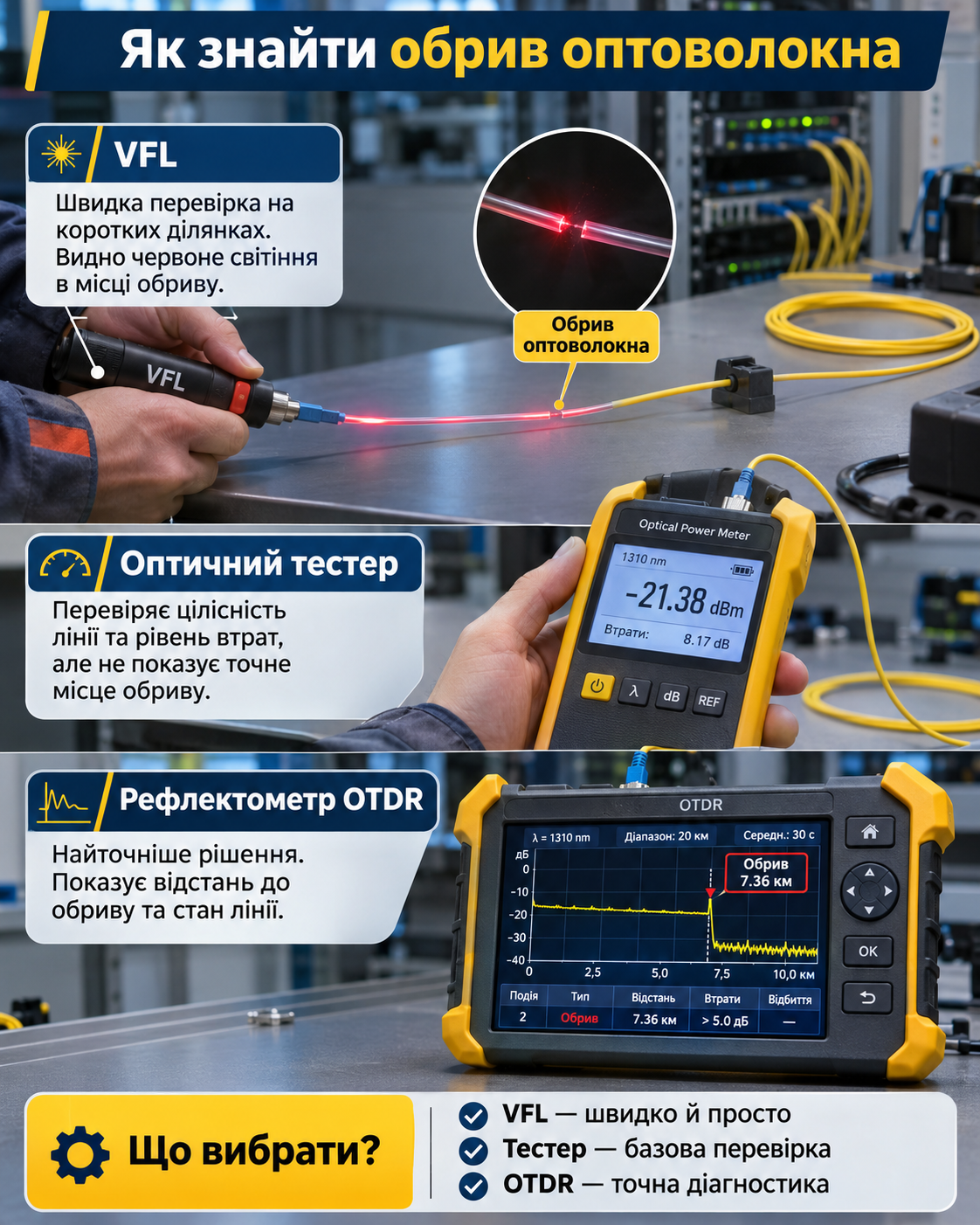
How to Find a Fiber Optic Cable Break: VFL, Optical Tester or OTDR
Fiber optic networks provide high-speed and reliable data transmission over long distances. However, even a properly installed fiber optic cable can be damaged during installation, maintenance, construction work or normal operation. As a result, the internet connection may stop working, communication between network switches may fail, equipment may display a LOS warning, or the optical signal level may drop significantly.
In such situations, an important question arises: how can you find a fiber optic cable break and determine exactly where the line is damaged? Different diagnostic instruments are used for this purpose, including Visual Fault Locators (VFL) and fiber optic tools, optical power meters, optical light sources and Optical Time Domain Reflectometers (OTDR).
Each instrument serves a different purpose. A VFL helps visually identify damage and check fiber continuity. An optical power meter measures the received optical signal level. An OTDR analyzes the fiber optic link, detects breaks and determines the distance to a problematic section.
In this guide, we will compare VFL, optical testers and OTDR instruments, explain how to test fiber optic cables measuring 100 meters, 1 km or 10 km, discuss what to do when the signal disappears, show how to diagnose SC and LC connections, and explain which tools are needed for professional fiber optic network maintenance.
Why Does a Fiber Optic Cable Lose Signal?
A missing optical signal does not always mean that the fiber is completely broken. The problem may be located in the cable itself, connectors, fusion splices, patch cords or active network equipment.
Common causes include:
- mechanical damage to the fiber optic cable;
- a complete break in one or more optical fibers;
- excessive bending of a cable or patch cord;
- fiber damage inside a termination box or splice closure;
- poor-quality fiber optic fusion splicing;
- contaminated fiber optic connector end faces;
- damaged SC, LC, FC or ST connectors;
- incorrect mating of UPC and APC connectors;
- poor contact or a faulty fiber optic adapter;
- a damaged fiber optic patch cord;
- a defective SFP module, media converter or other device;
- incorrect TX/RX connections;
- incompatible speeds, wavelengths or optical transceiver types.
Therefore, proper troubleshooting should begin with checking accessible connections, network equipment and optical signal levels rather than immediately digging up cables or opening splice closures.
What Instruments Are Used to Find Fiber Optic Cable Breaks?
Several types of testing instruments are used to diagnose fiber optic links.
| Instrument | What It Checks | Main Purpose |
|---|---|---|
| VFL — Visual Fault Locator | Fiber continuity and visible light leakage at damaged points | Finding accessible damage, severe bends and identifying individual fibers |
| OPM — Optical Power Meter | Received optical signal power | Checking optical power at a device input or an accessible network point |
| OLS + OPM or OLTS | Total insertion loss | Measuring attenuation between two ends of a fiber optic link |
| OTDR — Optical Time Domain Reflectometer | Distance to events, breaks, irregularities and splice points | Locating faults and analyzing the fiber optic route |
| VFL + Cleaning Tools | Accessible damage and connector condition | Initial troubleshooting of patch cords and optical connections |
Important: these instruments are not interchangeable. A VFL does not display the exact distance to a break, an optical power meter does not identify the location of damage, and an OTDR does not replace a complete end-to-end insertion loss measurement using an optical light source and power meter.
What Is a VFL and How Does It Help Find Fiber Optic Breaks?
A VFL (Visual Fault Locator) is an instrument used to visually identify faults in optical fibers. It sends visible red laser light into the fiber, typically at a wavelength of approximately 650 nm.
If the fiber contains a severe bend, crack, damaged connection or break, red light may escape at the fault location under certain conditions.
This can allow a technician to visually identify the problem without using complex testing equipment.
VFL instruments are commonly used for:
- checking fiber optic patch cord continuity;
- finding damage in accessible cable sections;
- identifying severe fiber bends;
- checking fibers inside termination boxes and patch panels;
- identifying a specific fiber among several fibers;
- troubleshooting short fiber optic connections;
- testing accessible sections of FTTH links;
- initial diagnostics after installation or repair.
However, the visibility of red light depends on the cable construction, jacket color, distance, type of damage and lighting conditions. Light leakage may not be visible through a thick black cable jacket, armored cable construction or protective conduit.
LW-FOTR-001 Visual Fault Locator: 10 mW, 650 nm
The Net-Server catalog includes the LW-FOTR-001 Fiber Optic Visual Fault Locator.
This compact instrument is designed for checking fiber optic continuity, identifying fibers and locating certain types of damage.
Main specifications:
- device type — VFL (Visual Fault Locator);
- wavelength — 650 nm;
- specified laser output power — 10 mW;
- advertised testing range — up to 10 km;
- operating modes — continuous light and flashing mode;
- universal connection for 2.5 mm ferrule connectors — SC, FC and ST;
- metal housing;
- power supply — compatible batteries.
Connecting LC connectors with 1.25 mm ferrules requires a compatible adapter or a suitable fiber optic patch cord.
Important: the manufacturer's advertised 10 km testing range indicates the potential propagation distance of test light under certain conditions. It does not guarantee that a technician will be able to see or precisely locate a cable break at that distance.
A VFL cannot measure the distance to a fault in meters. An OTDR is required to determine the location of a break along a long fiber optic route.
How to Test Fiber Optic Cable with a VFL: Step-by-Step Guide
Before testing, make sure that the fiber is disconnected from active optical equipment and light sources. A VFL should not be used on an operating optical link without an approved and compatible testing procedure.
Step 1. Identify the Fiber to Be Tested
Disconnect the required patch cord or fiber from the active optical port. Check the labeling and confirm that you are working with the correct fiber optic link.
Step 2. Inspect and Clean the Connector
Before connecting the VFL, inspect the connector end face using an appropriate fiber optic inspection tool and clean it if necessary.
A contaminated connector may reduce the transmission of test light and make troubleshooting more difficult.
Step 3. Connect the VFL
Connect the fiber optic connector to the appropriate port on the Visual Fault Locator.
The LW-FOTR-001 normally supports compatible 2.5 mm ferrule connectors. An appropriate adapter is required for LC connectors.
Step 4. Activate the Test Light
Enable continuous light or flashing mode according to the instrument manufacturer's instructions.
Flashing mode can make it easier to identify a particular fiber among multiple optical connections.
Step 5. Inspect Accessible Cable Sections
Examine the patch cord, connector areas, cable bends, termination boxes, splice trays and other accessible sections of the line.
If light escapes at a particular point, this may indicate fiber damage or a critical bend.
Never look directly into a fiber end face or the instrument's optical port. Even visible red laser radiation can be hazardous to the eyes.
Step 6. Record the Results
If a fault is identified, determine whether the damaged section can be repaired.
A damaged patch cord is usually easier to replace. Damage to the main fiber optic cable may require fusion splicing, installation of a splice closure or replacement of a cable section.
After completing the repair, test the link using appropriate optical measuring instruments.
Why Doesn't a VFL Always Show the Location of a Cable Break?
A VFL is useful for quick troubleshooting, but it has limitations.
Red light leakage may not be visible when:
- the damaged fiber is inside an opaque cable;
- the cable has an armored construction;
- the fiber is installed inside protective conduit;
- the break is located underground;
- light cannot reach the damaged section;
- the distance or total optical attenuation is too high;
- the fault does not produce visible light leakage;
- ambient lighting makes weak light leakage difficult to detect.
For example, if a fiber optic cable runs 150 meters between two buildings and has a black polyethylene jacket, a VFL may help check fiber continuity but may not reveal the exact location of the damage.
An OTDR is generally used to locate hidden breaks along enclosed cable routes.
What Is an Optical Power Meter (OPM)?
An OPM (Optical Power Meter) is an instrument used to measure optical signal power at a particular point in a fiber optic network.
The instrument typically displays the received optical power in dBm.
For example, if you need to determine whether an optical signal is reaching a receiver, an optical power meter can measure the actual signal power at an accessible connector.
Before measuring, you must select:
- the correct operating wavelength;
- the appropriate optical connector type;
- a compatible measurement adapter;
- the instrument's measurement range;
- the network operating mode;
- the acceptable optical power range of the receiver.
A standalone optical power meter measures the signal level. However, accurate end-to-end insertion loss measurements on a passive fiber optic link also require a suitable calibrated light source and a reference measurement procedure.
What Is the Difference Between dBm and dB?
Two units are frequently used in fiber optic testing: dBm and dB.
| Unit | Meaning | Example |
|---|---|---|
| dBm | Absolute optical power level referenced to 1 mW | Signal power at an optical receiver input |
| dB | Logarithmic ratio between power levels | Loss in a cable, connector, fusion splice or complete optical link |
For example, if the optical signal measures -5 dBm at the beginning of a link and -8 dBm after passing through the link under comparable conditions, the difference is 3 dB.
Actual measurements must account for the testing procedure, reference level, wavelength and the instruments' measurement uncertainty.
Important: a dBm reading alone does not determine whether network equipment will operate correctly. The measured power must be compared with the acceptable receiver input range of the specific SFP module, ONU/ONT or other optical device.
What Is an Optical Loss Test Set (OLTS)?
An OLTS (Optical Loss Test Set) is a testing system used to measure optical insertion loss. It typically consists of an optical light source and an optical power meter.
The light source transmits a signal through the fiber optic link, while the power meter measures the received power. Loss is calculated using an established reference level.
OLTS testing is used for:
- checking total fiber optic cable attenuation;
- acceptance testing after installation;
- comparing measured losses with the optical power budget;
- evaluating connection quality;
- testing a fiber optic link after repairs.
However, OLTS does not show the distance from the beginning of the cable to a fault.
If you need to determine the location of a break in meters, an OTDR is required.
What Is an Optical Time Domain Reflectometer (OTDR)?
An OTDR (Optical Time Domain Reflectometer) is a testing instrument used to analyze fiber optic links.
The instrument sends short optical pulses into the fiber and analyzes the light returning through backscattering and reflections.
Based on this information, the OTDR generates a trace showing the characteristics of the optical link as a function of distance.
An OTDR can help technicians:
- determine the length of a fiber optic link;
- locate the distance to a cable break;
- identify problematic cable sections;
- analyze losses at fusion splice points;
- evaluate reflections from connectors;
- detect certain bends and irregularities;
- check the condition of backbone fiber optic lines;
- compare test results before and after repairs.
OTDR testing is particularly useful for long outdoor fiber optic routes where cables run along utility poles, through ducts, inside cable chambers or underground.
How Does an OTDR Determine the Distance to a Cable Break?
An OTDR measures the time taken for a test light pulse to travel through the fiber and for reflected or backscattered light to return to the instrument.
Using this time and the optical propagation characteristics of the fiber, the OTDR calculates the distance to an event.
For example, if an OTDR trace identifies the end of the fiber or a possible break at 1,250 meters, this represents the approximate optical path length from the measurement point to that event.
However, 1,250 meters of optical fiber does not necessarily equal 1,250 meters of straight-line distance on the ground.
Factors to consider include:
- the actual cable route;
- cable slack stored near utility poles and manholes;
- cable loops inside splice closures;
- the length of launch cables or measurement patch cords;
- correct configuration of the fiber's refractive index;
- the measurement accuracy of the instrument.
For accurate fault location, OTDR results should be compared with cable route diagrams and installation documentation.
How to Test Fiber Optic Cable with an OTDR: Main Steps
The exact testing procedure depends on the OTDR model, network type and cable length. A typical workflow includes:
- Identify the fiber optic link and determine whether it uses Singlemode or Multimode fiber.
- Confirm that testing is permitted for the fiber and its current network operating condition.
- Inspect and clean the testing equipment connectors.
- Connect a suitable launch fiber if required.
- Select the operating wavelength.
- Configure the distance range and measurement parameters.
- Select the pulse width and averaging time.
- Run the measurement.
- Analyze the OTDR trace and event table.
- Compare the measured distances with the cable route documentation.
- Perform testing from the opposite end if necessary.
- Save the results for future maintenance and troubleshooting.
Suitable launch and receive fibers are often used to analyze the first and last connectors of a fiber optic link.
Important: a standard OTDR should not be connected to an active optical network without verifying that such testing is permitted. Operating PON networks require suitable instruments and testing modes designed for active fiber optic links.
Why Do Dead Zones Appear on an OTDR Trace?
After a strong reflection from an optical connector or another event, an OTDR receiver may temporarily be unable to distinguish closely spaced events.
These areas are called dead zones.
Because of dead zones, an OTDR may have difficulty resolving short patch cords, closely spaced connectors or events located near the beginning of a fiber optic link.
This is one reason why a VFL can be a useful complementary tool when troubleshooting short optical connections.
Appropriate pulse width settings and suitable launch and receive fibers help reduce the effect of OTDR dead zones.
VFL vs. OTDR: Which Is Better for 100 m, 1 km or 10 km?
The right instrument depends not only on cable length but also on the type of fault and the precision required.
| Fiber Optic Link Length | Suitable Instruments | Important Considerations |
|---|---|---|
| 1–10 m | VFL, connector inspection and cleaning, optical power meter | Useful for checking patch cords, accessible bends and connections |
| 50–100 m | VFL, optical light source and power meter | A VFL can help with initial diagnostics but cannot measure the distance to a hidden break |
| 150–500 m | VFL, OPM/OLTS, OTDR when needed | An OTDR with suitable resolution is used to locate hidden faults |
| 1–2 km | OPM/OLTS and OTDR | An OTDR helps determine the distance to the problematic section |
| 5–10 km and longer | OTDR with a suitable measurement range and appropriate testing equipment | Long fiber optic routes require correct measurement settings |
This table is a general guide, not a strict limitation for each instrument. Actual results depend on cable construction, fiber type, testing conditions and equipment specifications.
If you need to locate a break inside a concealed underground fiber optic cable measuring 1 km, an OTDR will usually be significantly more useful than a standard VFL.
How to Find a Fiber Optic Cable Break Between Two Network Switches
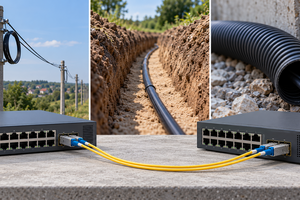
Consider a practical example. Switch A is installed in Building A, and Switch B is installed in Building B. Both switches use SFP modules and are connected by an approximately 200-meter fiber optic cable.
If the connection fails, troubleshooting should be performed step by step.
1. Check the Active Network Equipment
Make sure both switches are operating, the SFP modules are correctly installed and the relevant ports are enabled.
Check SFP module compatibility in terms of speed, fiber type, wavelength and connection configuration.
2. Check the Fiber Optic Patch Cords
A damaged patch cord is one possible cause of a failed optical connection.
Inspect the cables and connectors. If necessary, replace the patch cord with a known-good compatible one.
3. Check the TX/RX Connections
In conventional duplex optical connections, the transmitter of one device must be connected to the receiver of the other device.
If the fibers are crossed incorrectly, the optical link may fail to establish.
BiDi modules require a correctly matched pair with compatible transmit and receive wavelengths.
4. Inspect the Connectors and Adapters
A contaminated SC or LC connector end face can cause excessive optical loss.
Use appropriate fiber optic cleaning tools and then test the connection again.
5. Measure the Optical Signal Power
If an appropriate optical power meter is available, check the signal power at accessible test points.
Compare the results with the receiver's permitted optical power range.
6. Test the Fiber with a VFL
On a fiber disconnected from active equipment, a VFL can help identify accessible damage or verify the propagation of test light.
7. Use an OTDR If the Fault Location Is Unknown
If the cable is installed inside corrugated conduit, suspended between poles or buried underground, and the damaged section is not visible, an OTDR can help determine the distance to the fault.
Once the damage is located, technicians can repair the cable or use a spare fiber if the network design allows it.
How to Test an SC or LC Fiber Optic Patch Cord
Fiber optic patch cords can be damaged by excessive bending, pulling forces, contaminated connectors or incorrect connections.
To inspect a patch cord:
- Disconnect the patch cord from active equipment.
- Inspect the cable jacket and areas near the connectors.
- Check the condition and cleanliness of the connector end faces.
- Clean the connectors using a suitable fiber optic cleaning tool if necessary.
- Verify SC/LC and UPC/APC compatibility.
- Use a VFL for an initial continuity check.
- If required, measure optical loss with suitable testing equipment.
If a patch cord has obvious mechanical damage, replacing it is often the most practical solution.
Why Is Fiber Optic Connector Cleaning Important?
Even a small dust particle on a fiber optic connector end face can increase optical loss, cause unwanted reflections or damage the contact surface.
Specialized cleaning tools for SC, LC, FC and ST connectors, along with suitable lint-free materials, are used for maintenance.
The Net-Server fiber optic tools catalog includes equipment for cleaning optical connectors and other fiber optic components.
Basic recommendations:
- inspect connector end faces before mating;
- use a cleaner suitable for the ferrule size;
- never touch connector end faces with your fingers;
- do not use dirty cleaning wipes;
- avoid cleaning materials that leave lint;
- inspect connectors again after cleaning whenever possible;
- install protective dust caps on disconnected connectors.
A professional approach is to inspect the connector, clean it when necessary and inspect it again before making the connection.
How to Troubleshoot GPON and FTTH Fiber Optic Links
GPON and FTTH networks require special consideration because they may contain passive optical splitters, multiple operating wavelengths and active subscriber connections.
If the LOS indicator lights up on an ONU or ONT, this may indicate that the equipment is not receiving the required optical signal. However, the cause may range from a damaged patch cord to a problem within the service provider's network.
Initial troubleshooting includes checking:
- power supply to the ONU/ONT;
- the fiber optic patch cord condition;
- correct connection of SC/APC or the required connector type;
- connector cleanliness;
- absence of severe fiber bends;
- the condition of accessible fiber termination boxes;
- actual optical signal power using a suitable measuring instrument;
- possible issues within the provider's network.
Measuring optical power in an operating PON network may require a dedicated PON power meter supporting the relevant wavelengths and operating modes.
Fault location in networks containing optical splitters requires suitable OTDR equipment and testing procedures designed for such networks.
Warning: do not connect a standard VFL or OTDR directly to an active service provider network without permission and an approved testing procedure. Doing so may disrupt network operation or create a risk to equipment.
What If the Optical Signal Is Present but the Internet Is Not Working?
The presence of optical signal power does not necessarily mean that the network connection is functioning correctly.
Possible causes include:
- incompatible SFP modules;
- incorrect port speed;
- network switch configuration errors;
- incorrect TX/RX connections;
- insufficient or excessive optical power;
- unstable operation of an optical transmitter;
- network configuration problems;
- faulty active network equipment;
- service provider authentication or configuration issues.
Therefore, troubleshooting the physical fiber optic link should be distinguished from diagnosing the active network equipment and its configuration.
Common Mistakes When Searching for Fiber Optic Cable Breaks
- opening splice closures before checking patch cords;
- assuming that every internet outage is caused by a broken fiber;
- failing to inspect connector cleanliness;
- mating incompatible UPC and APC connectors;
- confusing a VFL with an OTDR;
- expecting a VFL to display the distance to a break;
- ignoring the opaque jacket of outdoor fiber optic cables;
- failing to check SFP module compatibility;
- using the wrong testing wavelength;
- not configuring the OTDR for the fiber optic route length;
- ignoring OTDR dead zones;
- not using appropriate launch fibers when required;
- failing to account for cable slack inside splice closures and manholes;
- not testing the link after completing repairs;
- connecting laser testing equipment to an active network without verifying safety.
Safety Precautions When Testing Fiber Optic Cable
Fiber optic testing instruments may use visible or invisible laser radiation. Appropriate safety precautions must always be followed during testing.
- never look directly into the end of an optical fiber;
- never direct laser radiation toward the eyes;
- do not look into an SFP module's optical port;
- verify the condition of the link before connecting testing equipment;
- use testing instruments according to the manufacturer's instructions;
- do not connect incompatible test sources to active networks;
- avoid testing unidentified fiber optic lines without confirming their purpose;
- follow the laser safety requirements for the specific instrument classification.
Particular care is required when using higher-power VFL devices, including 10 mW models. Their laser output must not be considered safe for direct eye exposure.
Products Commonly Purchased for Fiber Optic Troubleshooting
The following products may be useful for testing, maintaining and repairing fiber optic networks:
- LW-FOTR-001 Visual Fault Locator, 10 mW, 650 nm — for initial fiber continuity checks and locating accessible damage;
- fiber optic tools and connector cleaning equipment — for connector maintenance and fiber preparation;
- fiber optic cleaning accessories — for cleaning optical components;
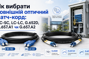
- SC and LC fiber optic patch cords — for replacing damaged connection cables;
- outdoor fiber optic patch cords — for suitable outdoor fiber optic connections;
- fiber optic adapters — for connecting compatible optical connectors;
- fiber optic pigtails — for repairing and terminating fibers through fusion splicing;
- fiber optic termination boxes — for organizing and protecting optical connections;
- fiber optic splice closures — for protecting fusion splices after cable repairs;
- fiber optic splice trays — for arranging protected fusion splice connections;
- fiber optic fusion splicers — for repairing and restoring damaged optical fibers;
- fiber optic cables — for replacing damaged network sections;
- SFP modules — for testing and replacing compatible active optical equipment.
Appropriate optical power meters, optical light sources and OTDR instruments are additionally used to measure actual attenuation or determine the distance to a fiber break. Such instruments must be selected according to the network type and testing requirements.
FAQ — Frequently Asked Questions
How Do You Find a Fiber Optic Cable Break?
First, inspect the active network equipment, patch cords and connectors. A VFL can be used to send visible red laser light through accessible fiber sections. An OTDR is used to determine the distance to a break along a longer fiber optic link.
Can You Find a Fiber Optic Break Without an OTDR?
Yes. In some cases, a VFL can reveal damage in an accessible cable section or patch cord. However, hidden breaks inside opaque cables, especially over long distances, often require an OTDR.
What Is a VFL?
VFL stands for Visual Fault Locator. It sends visible red light through an optical fiber and helps identify certain types of damage, severe bends and individual fibers.
Can a VFL Show the Exact Distance to a Break?
No. A standard VFL does not measure distance in meters. It helps visually detect certain faults and check the propagation of test light. An OTDR is required to determine the distance to a fault.
Can a VFL Find a Fiber Optic Break at 10 km?
Some VFL instruments advertise testing ranges of up to 10 km, but this does not guarantee that a fault can be visually located at that distance. Performance depends on the fiber, optical loss and type of damage. An OTDR is used for accurate fault location along long fiber optic routes.
Which Is Better: a VFL or an Optical Tester?
It depends on the task. A VFL is used for visual continuity checks and accessible damage. An optical power meter measures signal power, while an optical light source and power meter are used together to measure insertion loss.
Which Is Better: a VFL or an OTDR?
A VFL is often more convenient for checking short patch cords and visible damage. An OTDR is used for long cable routes and determining the distance to faults. The two instruments complement each other.
Can You Test a 100-Meter Fiber Optic Cable?
Yes. A VFL may be suitable for initial testing, while an optical light source and power meter can measure insertion loss. An OTDR can also be used if it has sufficient resolution and the correct testing procedure is followed.
Can You Locate an Underground Fiber Optic Cable Break?
An OTDR can help determine the approximate optical distance to a fault. The result is then compared with the actual cable route, manholes, splice closures and cable slack.
Why Is the Internet Not Working Even Though an Optical Signal Is Present?
Possible causes include insufficient or excessive optical power, incompatible SFP modules, incorrect TX/RX connections, defective active equipment or network configuration errors.
How Do You Test an LC Fiber Optic Patch Cord?
Disconnect the patch cord from active equipment, inspect and clean the connectors, and check for bending or mechanical damage. A VFL with a 2.5 mm port may require a special adapter for LC connectors with 1.25 mm ferrules.
Can You Use a VFL on an Active GPON Network?
A standard VFL should not be connected to an active PON network without permission and an appropriate testing procedure. Specialized instruments should be used for diagnosing operating PON links.
What Does LOS Mean on Fiber Optic Equipment?
LOS usually stands for Loss of Signal. The indicator may mean that the equipment is not receiving the required optical signal. The cause should be determined by checking the cable, connectors and network equipment.
Should Fiber Optic Connectors Be Cleaned Before Testing?
Yes. Contaminated connector end faces can affect optical loss and testing results. Connectors should be inspected and cleaned with suitable specialized tools when necessary.
Can an OTDR Check Fusion Splice Quality?
Yes. An OTDR can help evaluate losses at individual fusion splice points. For improved accuracy, technicians must consider the fiber type, instrument settings, measurement uncertainty and, when necessary, perform bidirectional testing.
What Should You Do After Finding a Fiber Optic Cable Break?
Depending on the type of damage, you can replace the patch cord, use a spare fiber, perform fusion splicing or replace the damaged cable section. The optical link should be tested again after repairs.
Useful Articles
- What Is an SFP Module and How to Choose One
- How Many Fibers Do You Need in a Fiber Optic Cable: 4, 8, 12, 24 or 48?
- How to Connect Two Network Switches with Fiber Optics: Aerial, Underground or in Conduit
- SC vs. LC: Which Fiber Optic Connector Should You Choose?
- UPC vs. APC: Differences Between Blue and Green Fiber Optic Connectors
- How to Choose an Outdoor Fiber Optic Patch Cord
Conclusion
To locate a fiber optic cable break correctly, it is important to understand the purpose of each diagnostic instrument and systematically check the components of the network.
A VFL helps quickly identify accessible faults, check fiber continuity and troubleshoot fiber optic patch cords.
An optical power meter measures optical signal levels and, when used together with a suitable light source, helps determine the total insertion loss of a fiber optic link.
An OTDR analyzes the optical route, determines the distance to cable breaks and examines fusion splices and other events along the link.
For short fiber optic connections, initial VFL testing and connector cleaning may be sufficient. Long, complex or concealed cable routes often require professional optical testing instruments.
Looking for tools to test and repair fiber optic cables? At Net-Server, you can find Visual Fault Locators, fiber optic tools, connector cleaners, patch cords, pigtails, termination boxes, splice closures and fusion splicing equipment for maintaining fiber optic networks.